
Horizontally Scaling for Data Volume with Sharding
This page describes the deployment and use of an InterSystems IRIS sharded cluster.
Overview of InterSystems IRIS Sharding
Sharding is a significant horizontal scalability feature of InterSystems IRIS. An InterSystems IRIS sharded cluster partitions both data storage and caching across a number of servers, providing flexible, inexpensive performance scaling for queries and data ingestion while maximizing infrastructure value through highly efficient resource utilization. Sharding is easily combined with the considerable vertical scaling capabilities of InterSystems IRIS, greatly widening the range of workloads for which InterSystems IRIS can provide solutions.
For a brief introduction to sharding that includes a hands-on exploration of deploying and using a sharded cluster, see Demo: Scaling for Data Volume with an InterSystems IRIS Sharded Cluster.
Elements of Sharding
Horizontally scaling via sharding can benefit a wide range of applications, but provides the greatest gains in use cases involving one or both of the following:
-
Large amounts of data retrieved from disk, complex processing of data, or both, for example as in analytic workloads
-
High-volume, high-velocity data ingestion
Sharding horizontally partitions large database tables and their associated indexes across multiple InterSystems IRIS instances, called data nodes, while allowing applications to access these tables through any one of those instances. Together, the data nodes form a sharded cluster. This architecture provides the following advantages:
-
Queries against a sharded table are run in parallel on all of the data nodes, with the results merged, aggregated, and returned as full query results to the application.
-
Because the data partitions are hosted by separate instances, each has a dedicated cache to serve its own partition of the data set, rather than a single instance’s cache serving the entire data set.
With sharding, the performance of queries against large tables is no longer constrained by the resources of a single system. By distributing both query processing and caching across multiple systems, sharding provides near-linear scaling of both compute and memory resources, allowing you to design and maintain a cluster tailored to your workload. When you scale out by adding data nodes, sharded data can be rebalanced across the cluster. The distributed data layout can be further exploited for parallel data loading and with third party frameworks.
A shard is a subset of a table's rows, with each row contained within exactly one shard, and all shards of a table containing roughly the same number of rows. Each data node hosts a data shard, which is composed of one shard of each sharded table on the cluster. A federated software component called the sharding manager keeps track of which shards (and therefore which table rows) are located on which data nodes and directs queries accordingly, as well as managing other sharded operations. Each table is automatically horizontally partitioned across the data nodes by using one of its fields as a shard key, which provides a deterministic method of distributing data evenly. A shard key is typically the table’s RowID (the default), but can also be a user-defined field or set of fields.
While sharded data is physically partitioned across the data nodes, it is all logically visible from on any data node (as are nonsharded data, metadata, and code). Each data node has a cluster namespace (identically named across the cluster) that provides transparent access to all data and code on the cluster; applications can connect to any node's cluster namespace and experience the full dataset as if it were local. Application connections should therefore be load balanced across all of the data nodes in the cluster to take greatest advantage of parallel query processing and partitioned caching.

Nonsharded data is stored only on the first data node configured (called data node 1, or just node 1). This distinction is transparent to the user except for the fact that more data is stored on node 1, but this difference is typically small. From the perspective of the application SQL, the distinction between sharded and nonsharded tables is transparent.
InterSystems IRIS mirroring can be used to provide high availability for the data nodes in a sharded cluster; a mirrored failover pair of InterSystems IRIS instances can be added to a cluster as easily as a single instance. For more information on deploying a mirrored sharded cluster, see Mirror Data Nodes for High Availability.
For advanced use cases in which extremely low query latencies are required, potentially at odds with a constant influx of data, compute nodes can be added to provide a transparent caching layer for servicing queries, separating the query and data ingestion workloads and improving the performance of both. Assigning multiple compute nodes per data node can further improve the cluster’s query throughput. For more information about compute nodes and instructions for deploying them, see Deploy Compute Nodes for Workload Separation and Increased Query Throughput.
Evaluating the Benefits of Sharding
InterSystems IRIS sharding can benefit a wide range of applications, but provides the greatest gains in use cases involving the following:
-
Relatively large data sets, queries that return large amounts of data, or both.
Sharding scales caching capacity to match data size by partitioning the cache along with the data, leveraging the memory resources of multiple systems. Each data node dedicates its database cache (global buffer pool) to a fraction of the data set, as compared to a single instance’s database cache being available for all of the data. The resulting improvement becomes most evident when the data in regular use is too big to fit in the database cache of a single nonsharded instance.
-
A high volume of complex queries doing large amounts of data processing.
Sharding scales query processing throughput by decomposing queries and executing them in parallel across multiple data nodes, leveraging the computing resources of multiple systems. The resulting improvement is most evident when queries against the cluster:
-
Read large amounts of data from persistent storage, and in particular have a high ratio of data retrieved to results returned.
-
Involve significant compute work (including aggregation, grouping, and sorting)
-
-
High-volume or high-speed data ingestion, or a combination.
Sharding scales data ingestion through the InterSystems IRIS JDBC driver’s use of direct connections to the data nodes for parallel loading, distributing ingestion across multiple instances. If the data can be assumed to be validated and uniqueness checking omitted, gains are enhanced.
Each of these factors on its own influences the potential gain from sharding, but the benefit may be enhanced where they combine. For example, a combination of large amounts of data ingested quickly, large data sets, and complex queries that retrieve and process a lot of data makes many of today’s analytic workloads very good candidates for sharding.
As previously noted, and discussed in more detail in Planning an InterSystems IRIS Sharded Cluster, combining InterSystems IRIS sharding with the use of vertical scaling to address some of the factors described in the foregoing may be most beneficial under many circumstances.
In the current release, sharding does not support workloads involving complex transactions requiring atomicity, and a sharded cluster cannot be used for such workloads.
Namespace-level Sharding Architecture
Older versions of this document described a sharding architecture involving a larger and different set of node types (shard master data server, shard data server, shard query server). This namespace-level architecture remains in place as the transparent foundation of the new node-level architecture, and is fully compatible with it. In the node-level architecture, the cluster namespace (identically named across the cluster) provides transparent access to all sharded and nonsharded data and code on the cluster; the master namespace, now located on the first data node, still provides access to metadata, nonsharded data, and code, but is fully available to all data nodes. This arrangement provides a more uniform and straightforward model that is simpler and more convenient to deploy and use.
You can deploy a namespace-level sharded cluster using the Sharding Configuration page of the Management Portal and the %SYSTEM.ShardingOpens in a new tab API; these procedures are described in Deploying the Namespace-level Architecture.
Deploying the Sharded Cluster
To provide you with simple ways to create your first cluster for evaluation and testing purposes, this section includes manual procedures for deploying a basic InterSystems IRIS sharded cluster consisting of nonmirrored data nodes, using either the Management Portal or the %SYSTEM.ClusterOpens in a new tab API to configure the cluster. These procedures are extended for adding compute nodes and mirroring in subsequent sections, as follows:
-
Compute nodes can be easily added to an existing cluster; if you are considering deploying compute nodes in production, the best approach is typically to evaluate the operation of your data node-only cluster before deciding whether it can benefit from their addition. For more information on planning and adding compute nodes, see Plan Compute Nodes and Deploy Compute Nodes for Workload Separation and Increased Query Throughput.
-
Other than adding failover (and optionally disaster recovery) capability to each data node and the possible minor impact of latency between failover members, a mirrored sharded cluster performs in exactly the same way as a nonmirrored cluster of the same number of data nodes. If you are interested in deploying a mirrored sharded cluster, see Mirror Data Nodes for High Availability for procedures.
InterSystems IRIS data platform also offers several methods for automated deployment of sharded clusters, which greatly simplify the process of deploying clusters of varying topology on a variety of platforms, including on-premises hardware, public and private clouds, and Kubernetes.
Regardless of the method you use to deploy a sharded cluster, the first steps are to decide how many data nodes are to be included in the cluster and plan the sizes of the database caches and globals databases on those nodes. When deploying manually, you also need to identify or provision the infrastructure that will host the cluster and deploy InterSystems IRIS on the hosts before configuring the cluster. Therefore, to deploy your basic cluster using the manual procedures in this section, start with these steps and then choose a manual configuration method, as follows:
-
Configure the cluster using either:
The instructions in this section:
-
Do not describe the deployment of a mirrored sharded cluster or of compute nodes. Mirrored deployment is covered in Mirror for High Availability, while Deploy Compute Nodes for Workload Separation and Increased Query Throughput provides instructions for using the API to add compute nodes to a basic cluster.
-
Deploy a node-level sharded cluster; for instructions for deploying a namespace-level cluster, see Deploying the Namespace-level Architecture.
These instructions assume you will deploy new InterSystems IRIS instances on the hosts you provisioned or identified before configuring the cluster, but can be adapted for use with existing instances, as long as the instances to be configured as cluster nodes and their hosts adhere to the requirements and guidelines described in the first four steps.
For an important discussion of load balancing a web server tier distributing application connections across data and (where applicable) compute nodes, see Load Balancing, Failover, and Mirrored Configurations.
For an important discussion of performance planning, including memory management and scaling, CPU sizing and scaling, and other considerations, see System Resource Planning and Management.
In the most typical sharded cluster configuration, each cluster node consists of one InterSystems IRIS instance on one physical or virtual system. This configuration is assumed in the procedures provided on this page.
InterSystems recommends the use of an LDAP server to implement centralized security across the nodes of a sharded cluster. For information about using LDAP with InterSystems IRIS, see LDAP Guide.
HealthShare Health Connect does not support sharding.
Automated Deployment Methods for Clusters
In addition to the manual procedures outlined in this section, InterSystems IRIS Data platform provides two methods for automated deployment of sharded clusters that are fully operational following deployment.
Deploy a Sharded Cluster Using the InterSystems Kubernetes Operator (IKO)
KubernetesOpens in a new tab is an open-source orchestration engine for automating deployment, scaling, and management of containerized workloads and services. You define the containerized services you want to deploy and the policies you want them to be governed by; Kubernetes transparently provides the needed resources in the most efficient way possible, repairs or restores the deployment when it deviates from spec, and scales automatically or on demand. The InterSystems Kubernetes Operator (IKO) extends the Kubernetes API with the IrisCluster custom resource, which can be deployed as an InterSystems IRIS sharded cluster, distributed cache cluster, or standalone instance, all optionally mirrored, on any Kubernetes platform.
The IKO isn’t required to deploy InterSystems IRIS under Kubernetes, but it greatly simplifies the process and adds InterSystems IRIS-specific cluster management capabilities to Kubernetes, enabling tasks like adding nodes to a cluster, which you would otherwise have to do manually by interacting directly with the instances.
For more information on using the IKO, see Using the InterSystems Kubernetes OperatorOpens in a new tab.
Deploy a Sharded Cluster Using Configuration Merge
The configuration merge feature, available on Linux and UNIX® systems, lets you vary the configurations of InterSystems IRIS containers deployed from the same image, or local instances installed from the same kit, by simply applying the desired declarative configuration merge file to each instance in the deployment.
This merge file, which can also be applied when restarting an existing instance, updates an instance’s configuration parameter file (CPF), which contains most of its configuration settings; these settings are read from the CPF at every startup, including the first one after an instance is deployed. When you apply configuration merge during deployment, you in effect replace the default CPF provided with the instance with your own updated version.
Using configuration merge, you can deploy a sharded cluster by calling separate merge files for the different node types, sequentially deploying data node 1, then the remaining data nodes, then (optionally) the compute nodes. (Because the instance configured as data node 1 must be running before the other data nodes can be configured, you must ensure that this instance is deployed and successfully started before other instances are deployed.) You can also automatically deploy a cluster of data nodes (optionally mirrored) using a single merge file if the deployment hosts have names ending in the regular expression you specify; following deployment of the data nodes, you can optionally deploy compute nodes using a separate merge file.
The IKO, described above, incorporates the configuration merge feature.
For information about using configuration merge in general and to deploy sharded clusters in particular, see Automating Configuration of InterSystems IRIS with Configuration Merge and ConfigShardedCluster.
Plan Data Nodes
Depending on the anticipated working set of the sharded data you intend to store on the cluster and the nature of the queries you will run against it, as few as four data nodes may be appropriate for your cluster. You can always add data nodes to an existing cluster and rebalance the sharded data (see Add Data Nodes and Rebalance Data), so erring on the conservative side is reasonable.
A good basic method for an initial estimate of the ideal number of data nodes needed for a production configuration (subject to resource limitations) is to calculate the total amount of database cache needed for the cluster and then determine which combination of server count and memory per server is optimal in achieving that, given your circumstances and resource availability. This is not unlike the usual sizing process, except that it involves dividing the resources required across multiple systems. (For an important discussion of performance planning, including memory management and scaling, CPU sizing and scaling, and other considerations, see System Resource Planning and Management.)
The size of the database cache required starts with your estimation of the total amount of sharded data you anticipate storing on the cluster, and of the amount of nonsharded data on the cluster that will be frequently joined with sharded data. You can then use these totals to estimate the working sets for both sharded data and frequently joined nonsharded data, which added together represent the total database caching capacity needed for all the data nodes in the cluster. This calculation is detailed in Planning an InterSystems IRIS Sharded Cluster.
Considering all your options regarding both number of nodes and memory per node, you can then configure enough data nodes so that the database cache (global buffer pool) on each data node equals, or comes close to equalling, its share of that capacity. Under many scenarios, you will be able to roughly determine the number of data nodes to start with simply by dividing the total cache size required by the memory capacity of the systems you available to deploy as cluster nodes.
All data nodes in a sharded cluster should have identical or at least closely comparable specifications and resources; parallel query processing is only as fast as the slowest data node. In addition, the configuration of all InterSystems IRIS instances in the cluster should be consistent; database settings such as collation and those SQL settings configured at instance level (default date format, for example) should be the same on all nodes to ensure correct SQL query results. Standardized procedures and the available automated deployment methods for sharded clusters can help ensure this consistency.
Because applications can connect to any data node's cluster namespace and experience the full dataset as if it were local, the general recommended best practice is to load balance application connections across all of the data nodes in a cluster. The IKO can automatically provision and configure a load balancer for the data nodes as needed under typical scenarios; if deploying a sharded cluster by other means, a load balancing mechanism is required. For an important discussion of load balancing a web server tier distributing application connections across data nodes, see Load Balancing, Failover, and Mirrored Configurations.
Estimate the Database Cache and Database Sizes
Before deploying your sharded cluster, determine the size of the database cache to be allocated on each data node. It is also useful to know the expected size of the data volume needed for the default globals database on each data node, so you can ensure that there is enough free space for expected growth.
When you deploy a sharded cluster using an automated deployment method, you can specify these settings as part of deployment. When you deploy manually using the Sharding API or the Management Portal, you can specify database cache size of each instance before configuring the sharded cluster, and specify database settings in your calls. Both manual deployment methods provide default settings.
Bear in mind that the sizes below are guidelines, not requirements, and that your estimates for these numbers are likely to be adjusted in practice.
Database Cache Sizes
As described in Planning an InterSystems IRIS Sharded Cluster, the amount of memory that should ideally be allocated to the database cache on a data node is that node’s share of the total of the expected sharded data working set, plus the overall expected working set of nonsharded data frequently joined to sharded data.
Globals Database Sizes
As described in Planning an InterSystems IRIS Sharded Cluster, the target sizes of the default globals databases are as follows:
-
For the cluster namespace — Each server’s share of the total size of the sharded data, according to the calculation described in that section, plus a margin for greater than expected growth.
-
For the master namespace on node 1 — The total size of nonsharded data, plus a margin for greater than expected growth.
All deployment methods configure the sizes of these databases by default, so there is no need for you to do so. However, you should ensure that the storage on which these databases are located can accommodate their target sizes.
Provision or Identify the Infrastructure
Provision or identify the needed number of networked host systems (physical, virtual, or cloud) — one host for each data node.
All data nodes in a sharded cluster should have identical or at least closely comparable specifications and resources; parallel query processing is only as fast as the slowest data node. (The same is true of compute nodes, although storage is not a consideration in their case.)
The recommended best practice is to load balance application connections across all of the data nodes in a cluster.
To maximize the performance of the cluster, it is a best practice to maximize network throughput by configuring low-latency network connections between all of the data nodes, for example by locating them on the same subnet in the same data center or availability zone. This procedure assumes that the data nodes are mutually accessible through TCP/IP, with a recommended minimum network bandwidth of 1 GB between all nodes and preferred bandwidth of 10 GB or more, if available.
Deploy InterSystems IRIS on the Data Node Hosts
This procedure assumes that each system hosts or will host a single InterSystems IRIS instance. You can configure existing instances instead of newly deployed instances in the final step, as long as each instance and its host meet the requirements described in this step.
All InterSystems IRIS instances in a sharded cluster must be of the same version, and all must have sharding licenses.
All instances should have their database directories and journal directories located on separate storage devices, if possible. This is particularly important when high volume data ingestion is concurrent with running queries. For guidelines for file system and storage configuration, including journal storage, see Storage Planning, File System Separation, and Journaling Best Practices.
The configuration of all InterSystems IRIS instances in the cluster should be consistent; database settings such as collation and those SQL settings configured at the instance level (default date format, for example) should be the same on all nodes to ensure correct SQL query results.
On each host system, do the following:
-
Deploy an instance of InterSystems IRIS, either by creating a container from an InterSystems-provided image (as described in Running InterSystems Products in Containers) or by installing InterSystems IRIS from a kit (as described in the Installation Guide).
-
Ensure that the storage device hosting the instance’s databases is large enough to accommodate the target globals database size, as described in Estimate the Database Cache and Database Sizes.
-
Allocate the database cache (global buffer pool) for the instance according to the size you determined in Estimate the Database Cache and Database Sizes. For the Management Portal procedure for allocating the database cache, see Memory and Startup Settings; you can also allocate the cache using the globals parameter, either by editing the instance’s configuration parameter file (CPF) or, on UNIX® and Linux platforms, deploying the instance with the desired value using a configuration merge file.
In some cases, it may also be advisable to increase the size of the shared memory heap on the cluster members. The shared memory heap can be configured either using the Management Portal, as described for the gmheap parameter, or in the instance’s CPF file using gmheap, as described above for globals.
Note:For general guidelines for estimating the memory required for an InterSystems IRIS instance’s routine and database caches as well as the shared memory heap, see Shared Memory Allocations.
Finally, configure the deployed instances as a sharded cluster using either the Management Portal (the next section) or the %SYSTEM.Cluster API (the one after that).
Configure the Cluster Using the Management Portal
Once you have completed the first four steps (planning the data nodes, estimating the database cache and database sizes, provisioning or identifying the infrastructure, and deploying InterSystems IRIS on the data node hosts), use this procedure to configure the instances you deployed (or the existing instances you prepared) in the previous step as a basic InterSystems IRIS sharded cluster of data nodes using the Management Portal.
Configure each node in the cluster using the following steps.
For information about opening the Management Portal in your browser, see the instructions for an instance deployed in a container or one installed from a kit.
Following the procedure, other Management Portal sharded cluster options are briefly discussed.
Configure Data Node 1
A sharded cluster is initialized when you configure the first data node, which is referred to as data node 1, or simply node 1. This data node differs from the others in that it stores the cluster’s nonsharded data, metadata, and code, and hosts the master namespace that provides all of the data nodes with access to that data. This distinction is completely transparent to the user except for the fact that more data is stored on the first data node, a difference that is typically small.
Once you have completed the first four steps (planning the data nodes, estimating the database cache and database sizes, provisioning or identifying the infrastructure, and deploying InterSystems IRIS on the data node hosts), use this procedure to configure the instances you deployed (or the existing instances you prepared) in the previous step as a basic InterSystems IRIS sharded cluster of data nodes using the Management Portal.
To configure node 1, follow these steps:
-
Open the Management Portal for the instance, select System Administration > Configuration > System Configuration > Sharding > Enable Sharding, and on the dialog that displays, click OK. (The value of the Maximum Number of ECP Connections setting need not be changed as the default is appropriate for virtually all clusters.)
-
Restart the instance. (There is no need to close the browser window or tab containing the Management Portal; you can simply reload it after the instance has fully restarted.)
-
Navigate to the Configure Node-Level page (System Administration > Configuration > System Configuration > Sharding > Configure Node-Level) and click the Configure button.
-
On the CONFIGURE NODE-LEVEL CLUSTER dialog, select Initialize a new sharded cluster on this instance and respond to the prompts that display as follows:
-
Select a Cluster namespace and Master namespace from the respective drop-downs, which both include
-
The default names (IRISCLUSTER and IRISDM) of new namespaces to be created, along with their default globals databases.
-
All eligible existing namespaces.
Initializing a sharded cluster creates by default cluster and master namespaces named IRISCLUSTER and IRISDM, respectively, as well as their default globals databases and the needed mappings. However, to control the names of the cluster and master namespaces and the characteristics of their globals databases, you can create one or both namespaces and their default databases before configuring the cluster, then specify them during the procedure. For example, given the considerations discussed in Globals Database Sizes, you may want to do this to control the characteristics of the default globals database of the cluster namespace, or shard database, which is replicated on all data nodes in the cluster.
Note:If the default globals database of an existing namespace you specify as the cluster namespace contains any globals or routines, initialization will fail with an error.
-
-
In some cases, the hostname known to InterSystems IRIS does not resolve to an appropriate address, or no hostname is available. If for this or any other reason, you want other cluster nodes to communicate with this node using its IP address instead, enter the IP address at the Override hostname prompt.
-
Do not select Enable Mirroring; the procedure for deploying a mirrored sharded cluster is provided in Mirror for High Availability
-
-
Click OK to return to the Configure Node-Level page, which now includes two tabs, Shards and Sharded Tables. Node 1 is listed under Shards, including its cluster address (which you will need in the next procedure), so you may want to leave the Management Portal for node 1 open on the Configure Node-Level page, for reference. Click Verify Shards to verify that node 1 is correctly configured.
Configure the Remaining Data Nodes
Once node 1 has been configured, configure each additional data node using these steps:
-
Open the Management Portal for the instance, select System Administration > Configuration > System Configuration > Sharding > Enable Sharding, and on the dialog that displays, click OK. (The value of the Maximum Number of ECP Connections setting need not be changed as the default is appropriate for virtually all clusters.)
-
Restart the instance. (There is no need to close the browser window or tab containing the Management Portal; you can simply reload it after the instance has fully restarted.)
-
Navigate to the Configure Node-Level page (System Administration > Configuration > System Configuration > Sharding > Configure Node-Level) and click the Configure button.
-
On the CONFIGURE NODE-LEVEL CLUSTER dialog, select Add this instance to an existing sharded cluster and respond to the prompts that display as follows:
-
Enter the cluster URL, which is the address displayed for node 1 on the Shards tab of the Configure Node-Level page (as described in the previous procedure). The cluster URL consists of the node 1 host’s identifier — either hostname or IP address (if you provided the IP address in the previous procedure) — plus the InterSystems IRIS instance’s superserver port and the name of the cluster namespace, for example clusternode011.acmeinternal.com:1972:IRISCLUSTER. (The name of the cluster namespace can be omitted if it is the default IRISCLUSTER.)
Note:From the perspective of another node (which is what you need in this procedure), the superserver port of a containerized InterSystems IRIS instance depends on which host port the superserver port was published or exposed as when the container was created. For details on and examples of this, see Running an InterSystems IRIS Container with Durable %SYS and Running an InterSystems IRIS Container: Docker Compose Example and see Container networkingOpens in a new tab in the Docker documentation.
The default superserver port number of a kit-installed InterSystems IRIS instance that is the only such on its host is 1972; when multiple instances are installed, superserver port numbers range from 51776 upwards. To see or change an the instance’s superserver port number, select System Administration > Configuration > System Configuration > Memory and Startup in the instance’s Management Portal.
-
Select data at the Role prompt to configure the instance as a data node.
-
In some cases, the hostname known to InterSystems IRIS does not resolve to an appropriate address, or no hostname is available. If for this or any other reason, you want other cluster nodes to communicate with this node using its IP address instead, enter the IP address at the Override hostname prompt.
-
Do not select Mirrored cluster; the procedure for deploying a mirrored sharded cluster is provided in Mirror for High Availability
-
-
Click OK to return to the Configure Node-Level page, which now includes two tabs, Shards and Sharded Tables. The data nodes you have configured so far are listed under Shards, starting with node 1. Click Verify Shards to verify that the data node is correctly configured and can communicate with the others.
Note:If you have many data nodes to configure, you can make the verification operation automatic by clicking the Advanced Settings button and selecting Automatically verify shards on assignment on the ADVANCED SETTINGS dialog. Other settings in this dialog should be left at the defaults when you deploy a sharded cluster.
Management Portal Sharding Options
Use the Rebalance button to display the REBALANCE dialog, which lets you redistribute sharded data evenly across all data nodes, including those recently added to an existing cluster. (You cannot query sharded tables while a rebalancing operation is running.) For details about rebalancing data, see Add Data Nodes and Rebalance Data.
The ADVANCED SETTINGS dialog, which you can display by clicking the Advanced Settings button on the Configure Node-Level page, provides the following options:
-
Select Automatically verify shards on assignment to make verification automatic following configuration of a new cluster node.
-
Change the cluster’s sharded query execution modeOpens in a new tab from the default asynchronous to synchronous; for a discussion of the effects of this, see Including Compute Nodes in Mirrored Clusters for Transparent Query Execution Across Failover.
-
Change the shard connection timeoutOpens in a new tab from the default of 60 seconds.
-
Use data node 1 host’s IP addressOpens in a new tab to identify it in cluster communications, rather than its hostname.
-
Change the number of times the cluster should retry connecting to a mirrored shardOpens in a new tab from the default of one.
-
Change the maximum number of ECP connections for the local node. The total number of nodes in the cluster cannot exceed this setting, which is set to 64 when you use the Enable Sharding Management Portal option, as described at the start of each of the two steps in this section.
-
Set the cluster to ignore errors during DROP TABLE operationsOpens in a new tab.
The Sharded Tables tab on the Configure Node-Level page display information about all of the sharded tables on the cluster.
Configure the Cluster Using the %SYSTEM.Cluster API
Use the following procedure to configure the instances you deployed (or the existing instances you prepared) in the previous step as a basic InterSystems IRIS sharded cluster of data nodes using the %SYSTEM.Cluster API. You will probably find it useful to refer to the %SYSTEM.Cluster class documentationOpens in a new tab in the InterSystems Class Reference. (As with all classes in the %SYSTEM package, the %SYSTEM.ClusterOpens in a new tab methods are also available through $SYSTEM.Cluster.)
Configure each node in the cluster using the following steps:
Configure Node 1
A sharded cluster is initialized when you configure the first data node, which is referred to as data node 1, or simply node 1. This data node differs from the others in that it stores the cluster’s nonsharded data, metadata, and code, and hosts the master namespace that provides all of the data nodes with access to that data. This distinction is completely transparent to the user except for the fact that more data is stored on the first data node, a difference that is typically small.
To configure node 1, open the InterSystems Terminal for the instance and call the $SYSTEM.Cluster.Initialize()Opens in a new tab method, for example:
set status = $SYSTEM.Cluster.Initialize()
To see the return value (for example, 1 for success) for the each API call detailed in these instructions, enter:
zw status
Reviewing status after each call is a good general practice, as a call might fail silently under some circumstances. If a call does not succeed (status is not 1), display the user-friendly error message by entering:
do $SYSTEM.Status.DisplayError(status)
The Initialize() call creates the master and cluster namespaces (IRISDM and IRISCLUSTER, respectively) and their default globals databases, and adds the needed mappings. Node 1 serves as a template for the rest of the cluster; the name of the cluster namespace, the characteristics of its default globals database (also called the shard database), and its mappings are directly replicated on the second data node you configure, and then directly or indirectly on all other data nodes. The SQL configuration settings of the instance are replicated as well.
To control the names of the cluster and master namespaces and the characteristics of their globals databases, you can specify existing namespaces as the cluster namespace, master namespace, or both by including one or both names as arguments. For example:
set status = $SYSTEM.Cluster.Initialize("CLUSTER","MASTER",,)
When you do this, the existing default globals database of each namespace you specify remains in place. This allows you to control the characteristics of the shard database, which are then replicated on other data nodes in the cluster.
If the default globals database of an existing namespace you specify as the cluster namespace contains any globals or routines, initialization will fail with an error.
By default, any host can become a cluster node; the third argument to Initialize() lets you specify which hosts can join the cluster by providing a comma-separated list of IP addresses or hostnames. Any node not in the list cannot join the cluster.
In some cases, the hostname known to InterSystems IRIS does not resolve to an appropriate address, or no hostname is available. If for this or any other reason, you want other cluster nodes to communicate with this node using its IP address instead, include the IP address as the fourth argument. (You cannot supply a hostname as this argument, only an IP address.) In either case, you will use the host identifier (hostname or IP address) to identify node 1 when configuring the second data node; you will also need the superserver (TCP) port of the instance.
From the perspective of another node (which is what you need in this procedure), the superserver port of a containerized InterSystems IRIS instance depends on which host port the superserver port was published or exposed as when the container was created. For details on and examples of this, see Running an InterSystems IRIS Container with Durable %SYS and Running an InterSystems IRIS Container: Docker Compose Example and see Container networkingOpens in a new tab in the Docker documentation.
The default superserver port number of a kit-installed InterSystems IRIS instance that is the only such on its host is 1972. To see or set the instance’s superserver port number, select System Administration > Configuration > System Configuration > Memory and Startup in the instance’s Management Portal. (For information about opening the Management Portal in your browser, see the instructions for an instance deployed in a container or one installed from a kit.)
The Initialize() method returns an error if the InterSystems IRIS instance is already a node in a sharded cluster, or is a mirror member.
Configure the Remaining Data Nodes
To configure each additional data node, open the Terminal for the InterSystems IRIS instance and call the $SYSTEM.Cluster.AttachAsDataNode()Opens in a new tab method, specifying the hostname of an existing cluster node (node 1, if you are configuring the second node) and the superserver port of its InterSystems IRIS instance, for example:
set status = $SYSTEM.Cluster.AttachAsDataNode("IRIS://datanode1:1972")
If you supplied an IP address as the fourth argument to Initialize() when initializing node 1, use the IP address instead of the hostname to identify node 1 in the first argument, for example:
set status = $SYSTEM.Cluster.AttachAsDataNode("IRIS://100.00.0.01:1972")
For important information about determining the correct superserver port to specify, see the previous step, Configure Node 1.
The AttachAsDataNode() call does the following:
-
Creates the cluster namespace and shard database, configuring them to match the settings on the template node (specified in the first argument), as described in Configure Node 1, and creating the needed mappings, including those to the globals and routines databases of the master namespace on node 1 (including any user-defined mappings).
-
Sets all SQL configuration options to match the template node.
-
Because this node may later be used as the template node for AttachAsDataNode(), sets the list of hosts eligible to join the cluster to those you specified (if any) in the Initialize() call on node 1.
If a namespace of the same name as the cluster namespace on the template node exists on the new data node, it and its globals database are used as the cluster namespace and shard database, and only the mappings are replicated. If the new node is subsequently used as the template node, the characteristics of these existing elements are replicated.
The AttachAsDataNode() call returns an error if the InterSystems IRIS instance is already a node in a sharded cluster or is a mirror member, or if the template node specified in the first argument is a mirror member.
As noted in the previous step, the hostname known to InterSystems IRIS may not resolve to an appropriate address, or no hostname is available. To have other cluster nodes communicate with this node using its IP address instead, include the IP address as the second argument. (You cannot supply a hostname as this argument, only an IP address.)
When you have configured all of the data nodes, you can call the $SYSTEM.Cluster.ListNodes()Opens in a new tab method to list them, for example:
set status = $system.Cluster.ListNodes()
NodeId  NodeType    Host          Port
1       Data        datanode1     1972
2       Data        datanode2     1972
3       Data        datanode3     1972
As shown, data nodes are assigned numeric IDs representing the order in which they are attached to the cluster.
The recommended best practice is to load balance application connections across all of the data nodes in a cluster.
For information about adding compute nodes to your cluster, see Deploy Compute Nodes for Workload Separation and Increased Query Throughput.
Creating Sharded Tables and Loading Data
Once the cluster is fully configured, you can plan and create the sharded tables and load data into them. The steps involved are as follows:
Evaluate Existing Tables for Sharding
Although the ratio of sharded to nonsharded data on a cluster is typically high, when planning the migration of an existing schema to a sharded cluster it is worth remembering that not every table is a good candidate for sharding. In deciding which of your application’s tables to define as sharded tables and which to define as nonsharded tables, your primary considerations should be improving query performance and/or the rate of data ingestion, based on the following factors (which are also discussed in Evaluating the Benefits of Sharding). As you plan, remember that the distinction between sharded and nonsharded tables is totally transparent to the application SQL; like index selection, sharding decisions have implications for performance only.
-
Overall size — All other things being equal, the larger the table, the greater the potential gain.
-
Data ingestion — Does the table receive frequent and/or large INSERT statements? Parallel data loading means sharding can improve their performance.
-
Query volume — Which tables are queried most frequently on an ongoing basis? Again, all other things being equal, the higher the query volume, the greater the potential performance improvement.
-
Query type — Among the larger tables with higher query volume, those that frequently receive queries that read a lot of data (especially with a high ratio of data read to results returned) or do a lot of computing work are excellent candidates for sharding. For example, is the table frequently scanned by broad SELECT statements? Does it receive many queries involving aggregate functions?
Having identified some good candidates for sharding, review the following considerations:
-
Frequent joins — As discussed in Choose a Shard Key, tables that are frequently joined can be sharded with equivalent shard keys to enable cosharded joins, so that joining can be performed locally on individual shards, enhancing performance. Review each frequently-used query that joins two large tables with an equality condition to evaluate whether it represents an opportunity for a cosharded join. If the queries that would benefit from cosharding the tables represent a sizeable portion of your overall query workload, these joined tables are good candidates for sharding.
However, when a large table is frequently joined to a much smaller one, sharding the large one and making the small one nonsharded may be most effective. Careful analysis of the frequency and query context of particular joins can be very helpful in choosing which tables to shard.
-
Unique constraints — A unique constraint on a sharded table can have a significant negative impact on insert/update performance unless the shard key is a subset of the unique key; see Choose a Shard Key for more information.
Regardless of other factors, tables that are involved in complex transactions requiring atomicity should never be sharded.
Create Sharded Tables
Sharded tables (as well as nonsharded tables) can be created in the cluster namespace on any node, using a SQL CREATE TABLE statement containing a sharding specification, which indicates that the table is to be sharded and with what shard key — the field or fields that determine which rows of a sharded table are stored on which shards. Once the table is created with the appropriate shard key, which provides a deterministic method of evenly distributing the table’s rows across the shards, you can load data into it using INSERT and dedicated tools. Additionally, you can convert a non-sharded table to a sharded table using the ALTER TABLE command with the CONVERT option; such a conversion requires you to choose a shard key.
Choose a Shard Key
By default, when you create a sharded table and do not specify a shard key, data is loaded into it using the system-assigned RowID as the shard key; for example, with two shards, the row with RowID=1 would go on one shard and the one with RowID=2 would go on the other, and so on. This is called a system-assigned shard key, or SASK, and is often the simplest and most effective approach because it offers the best guarantee of an even distribution of data and allows the most efficient parallel data loading.
By default, the RowID field is named ID and is assigned to column 1. If a user-defined field named ID is added, the RowID field is renamed to ID1 when the table is compiled, and it is the user-defined ID field that is used by default when you shard without specifying a key.
You also have the option of specifying one or more fields as the shard key when you create a sharded table; this is called a user-defined shard key, or UDSK. You might have good opportunities to use UDSKs if your schema includes semantically meaningful unique identifiers that do not correspond to the RowID, for example when several tables in a schema contain an accountnumber field.
An additional consideration concerns queries that join large tables. Every sharded query is decomposed into shard-local queries, each of which is run independently and locally on its shard and needs to see only the data that resides on that shard. When the sharded query involves one or more joins, however, the shard-local queries typically need to see data from other shards, which requires more processing time and uses more of the memory allocated to the database cache. This extra overhead can be avoided by enabling a cosharded join, in which the rows from the two tables that will be joined are placed on the same shard. When a join is cosharded, a query involving that join is decomposed into shard-local queries that join only rows on the same shard and thus run independently and locally, as with any other sharded query.
You can enable a cosharded join using one of two approaches:
-
Specify equivalent UDSKs for two tables.
-
Use a SASK for one table and the coshard with keywords and the appropriate UDSK with another.
To use equivalent UDSKs, simply specify the frequently joined fields as the shard keys for the two tables. For example, suppose you will be joining the CITATION and VEHICLE tables to return the traffic citations associated with each vehicle, as follows:
SELECT * FROM citation, vehicle where citation.vehiclenumber = vehicle.vin
To make this join cosharded, you would create both tables with the respective equivalent fields as the shard keys:
CREATE TABLE VEHICLE (make VARCHAR(30) not null, model VARCHAR(20) not null,
  year INT not null, vin VARCHAR(17) not null, shard key (vin))

CREATE TABLE CITATION(citationid VARCHAR(8) not null, date DATE not null,
  licensenumber VARCHAR(12) not null, plate VARCHAR(10) not null,
  vehiclenumber VARCHAR(17) not null, shard key (vehiclenumber))
Because the sharding algorithm is deterministic, this would result in both the VEHICLE row and the CITATION rows (if any) for a given VIN (a value in the vin and vehiclenumber fields, respectively) being located on the same shard (although the field value itself does not in any way determine which shard each set of rows is on). Thus, when the query cited above is run, each shard-local query can execute the join locally, that is, entirely on its shard. A join cannot be cosharded in this manner unless it includes an equality condition between the two fields used as shard keys. Likewise, you can use multiple-field UDSKs to enable a cosharded join, as long as the shard keys for the respective tables have same number of fields, in the same order, of types that allow the field values to be compared for equality.
The other approach, which is effective in many cases, involves creating one table using a SASK, and then another by specifying the coshard with keywords to indicate that it is to be cosharded with the first table, and a shard key with values that are equivalent to the system-assigned RowID values of the first table. For example, you might be frequently joining the ORDER and CUSTOMER tables in queries like the following:
SELECT * FROM orders, customers where orders.customer = customers.%ID
In this case, because the field on one side of the join represents the RowID, you would start by creating that table, CUSTOMER, with a SASK, as follows:
CREATE TABLE CUSTOMER (firstname VARCHAR(50) not null, lastname VARCHAR(75) not null,
  address VARCHAR(50) not null, city VARCHAR(25) not null, zip INT, shard)
To enable the cosharded join, you would then shard the ORDER table, in which the customer field is defined as a reference to the CUSTOMER table, by specifying a coshard with the CUSTOMER table on that field, as follows:
CREATE TABLE ORDER (date DATE not null, amount DECIMAL(10,2) not null,
  customer CUSTOMER not null, shard key (customer) coshard with CUSTOMER)
As with the UDSK example previously described, this would result in each row from ORDER being placed on the same shard as the row from CUSTOMER with RowID value matching its customerid value (for example, all ORDER rows in which customerid=427 would be placed on the same shard as the CUSTOMER row with ID=427). A cosharded join enabled in this manner must include an equality condition between the ID of the SASK-sharded table and the shard key specified for the table that is cosharded with it.
Generally, the most beneficial cosharded joins can be enabled using either of the following, as indicated by your schema:
-
SASKs representing structural relationships between tables and the coshard with keywords, as illustrated in the example, in which customerid in the ORDER table is a reference to RowID in the CUSTOMER table.
-
UDSKs involving semantically meaningful fields that do not correspond to the RowID and so cannot be cosharded using coshard with, as illustrated by the use of the equivalent vin and vehiclenumber fields from the VEHICLE and CITATION tables. (UDSKs involving fields that happen to be used in many joins but represent more superficial or adhoc relationships are usually not as helpful.)
Like queries with no joins and those joining sharded and nonsharded data, cosharded joins scale well with increasing numbers of shards, and they also scale well with increasing numbers of joined tables. Joins that are not cosharded perform well with moderate numbers of shards and joined tables, but scale less well with increasing numbers of either. For these reasons, you should carefully consider cosharded joins at this stage, just as, for example, indexing is taken into account to improve performance for frequently-queried sets of fields.
When selecting shard keys, bear in mind these general considerations:
-
The shard key of a sharded table cannot be changed, and its values cannot be updated.
-
All other things being equal, a balanced distribution of a table’s rows across the shards is beneficial for performance, and the algorithms used to distribute rows achieve the best balance when the shard key contains large numbers of different values but no major outliers (in terms of frequency); this is why the default RowID typically works so well. A well-chosen UDSK with similar characteristics may also be effective, but a poor choice of UDSK may lead to an unbalanced data distribution that does not significantly improve performance.
-
When a large table is frequently joined to a much smaller one, sharding the large one and making the small one nonsharded may be more effective than enabling a cosharded join.
Evaluate Unique Constraints
When a sharded table has a unique constraint (see Field Constraint and Unique Fields Constraint), uniqueness is guaranteed across all shards. Generally, this means uniqueness must be enforced across all shards for each row inserted or updated, which substantially slows insert/update performance. When the shard key is a subset of the fields of the unique key, however, uniqueness can be guaranteed across all shards by enforcing it locally on the shard on which a row is inserted or updated, avoiding any performance impact.
For example, suppose an OFFICES table for a given campus includes the buildingnumber and officenumber fields. While building numbers are unique within the campus, and office numbers are unique within each building, the two must be combined to make each employee’s office address unique within the campus, so you might place a unique constraint on the table as follows:
CREATE TABLE OFFICES (countrycode CHAR(3), buildingnumber INT not null, officenumber INT not null,
  employee INT not null, CONSTRAINT address UNIQUE (buildingname,officenumber))
If the table is to be sharded, however, and you want to avoid any insert/update impact on performance, you must use buildingnumber, officenumber, or both as the shard key. For example, if you shard on buildingnumber (by adding shard key (buildingnumber) to the statement above), all rows for each building are located on the same shard, so when inserting a row for the employee whose address is “building 10, office 27”, the uniqueness of the address can be enforced locally on the shard containing all rows in which buildingnumber=10; if you shard on officenumber, all rows in which officenumber=27 are on the same shard, so the uniqueness of “building 10, office 27” can be enforced locally on that shard. On the other hand, if you use a SASK, or employee as a UDSK, any combination of buildingnumber and officenumber may appear on any shard, so the uniqueness of “building 10, office 27” must be enforced across all shards, impacting performance.
For these reasons, you may want to avoid defining unique constraints on a sharded table unless one of the following is true:
-
All unique constraints are defined with the shard key as a subset (which may not be as effective generally as a SASK or a different UDSK).
-
Insert and update performance is considered much less important than query performance for the table in question.
Enforcing uniqueness in application code (for example, based on some counter) can eliminate the need for unique constraints within a table, simplifying shard key selection.
Create the Tables
Create the empty sharded tables using standard CREATE TABLE statements (see CREATE TABLE) in the cluster namespace on any data node in the cluster. As shown in the examples in Choose a Shard Key, there are two types of sharding specifications when creating a table:
-
To shard on the system-assigned shard key (SASK), include the shard keyword in the CREATE TABLE statement.
-
To shard on a user-defined shard key (UDSK), follow shard with the key keyword and the field or fields to shard on, for example shard key (customerid, purchaseid).
If the PK_IS_IDKEY option is set when you create a table, as described in Defining the Primary Key, the table’s RowID is the primary key; in such a case, using the default shard key means the primary key is the shard key. The best practice, however, if you want to use the primary key as the shard key, is to explicitly specify the shard key, so that there is no need to determine the state of this setting before creating tables.
You can display a list of all of the sharded tables on a cluster, including their names, owners, and shard keys, by navigating to the Sharding Configuration page of the Management Portal (System Administration > Configuration > System Configuration > Sharding Configuration) on node 1 or another data node, selecting the cluster namespace, and selecting the Sharded Tables tab. For a table you have loaded with data, you can click the Details link to see how many of the table’s rows are stored on each data node in the cluster.
The following constraints apply to sharded table creation:
-
You cannot use ALTER TABLE to make an existing nonsharded table into a sharded table (you can however use ALTER TABLE to alter a sharded table).
-
The SHARD KEY fields must be of numeric or string data types. The only collations currently supported for shard key fields are exact, SQLString, and SQLUpper, with no truncation.
-
All data types are supported except the ROWVERSION field and SERIAL (%Counter) fields.
-
A sharded table cannot include %CLASSPARAMETER VERSIONPROPERTYOpens in a new tab.
For further details on the topics and examples in this section, see CREATE TABLE.
In addition to using DDL to define sharded tables, you can define classes as sharded using the Sharded class keyword; for details, see Defining a Sharded Table by Creating a Persistent Class. The class compiler has been extended to warn against using class definition features incompatible with sharding (such as customized storage definitions) at compile time. More developed workload mechanisms and support for some of these incompatible features will be introduced in upcoming versions of InterSystems IRIS.
Load Data Onto the Cluster
Data can be loaded into sharded tables through any InterSystems IRIS interface that supports SQL. Rapid bulk loading of data into sharded tables is supported by the transparent parallel load capability built into the InterSystems IRIS JDBC driver. These options are described in the following:
-
You can load data into the empty sharded tables on your cluster through any InterSystems IRIS interface that supports SQL, such as a JDBC client tool or the SQL Shell. The LOAD DATA command, which is intended for rapid population of a table with well-validated data, loads from a table or file. You can also load data using one or more INSERT statements, including INSERT SELECT FROM.
-
The InterSystems IRIS JDBC driver implements specific optimizations for loading sharded tables. When preparing an INSERT statement into a sharded table, the JDBC client automatically opens direct connections to every data node and distributes the inserted rows across them, significantly enhancing performance without requiring any specific configuration or API calls. Any application loading sharded tables using JDBC transparently benefit from this capability.
Note:For most data loading operations, the JDBC driver uses direct connections to the data nodes brokered by the cluster. This requires the driver client to reach the data nodes at the IP addresses or hostnames with which they were assigned to the cluster, and means you cannot execute such queries if this is not possible.
Create and Load Nonsharded Tables
As with sharded tables, you can create nonsharded tables on any data node, and load data into them, using your customary methods. These tables are immediately available to the cluster for both nonsharded queries and sharded queries that join them to sharded tables. (This is in contrast to architectures in which nonsharded tables must be explicitly replicated to each node that may need them.) See Evaluate Existing Tables for Sharding for guidance in choosing which tables to load as nonsharded.
Querying the Sharded Cluster
The master namespace and the sharded tables it contains are fully transparent, and SQL queries involving any mix of sharded and nonsharded tables in the master namespace are no different from any SQL queries against any tables in an InterSystems IRIS namespace. No special query syntax is required to identify sharded tables or shard keys. Queries can join multiple sharded tables, as well as sharded and nonsharded tables. Everything is supported except what is specified in the following, which represent limitations and restrictions in the initial version of the InterSystems IRIS sharded cluster; the goal is that they will all be removed.
-
The only referential integrity constraints that are enforced for sharded tables are foreign keys when the two tables are cosharded, and the only referential action supported is NO ACTION.
-
Shard key fields must be of numeric or string data types. The only collations currently supported for shard key fields are exact, SQLString, and SQLUpper, with no truncation.
-
Row-level security for sharded tables is not currently supported.
-
Linked tables sourcing their content through a SQL Gateway connection cannot be sharded.
-
Use of the following InterSystems IRIS SQL extensions is not currently supported:
-
Aggregate function extensions including %FOREACH, and %AFTERHAVING.
-
Nested aggregate functions.
-
Queries with both an aggregate function and a nonaggregated field in the SELECT or HAVING clauses, unless this nonaggregated field also appears as a GROUP item in the GROUP BY clause.
-
The FOR SOME %ELEMENT predicate condition.
-
The %INORDER keyword.
-
If you want to explicitly purge cached queries on the data nodes, you can either purge all cached queries from the master namespace, or purge cached queries for a specific table. Both of these actions propagate the purge to the data nodes. Purging of individual cached queries is never propagated to the data nodes.
When queries return time-out errors and/or ECP connection issues are reported in messages.log, these are typically caused by networking issues. Users are advised to call the $SYSTEM.Sharding.VerifyShards()Opens in a new tab method of the %SYSTEM.Sharding API, which will test and try to restore connectivity, reporting some diagnostic information in the process.
When queries report privilege errors, these may be due to a mismatch between user-assigned privileges on the different shards, such as SELECT privileges on a particular table or view. Users are advised to verify and synchronize these on each server. A future version of IRIS will automate this process.
Additional Sharded Cluster Options
Sharding offers many configurations and options, suitable to your needs. This section provides brief coverage of additional options of interest, including:
For further assistance in evaluating the benefits of these options for your cluster, please contact the InterSystems Worldwide Response Center (WRC)Opens in a new tab.
Add Data Nodes and Rebalance Data
InterSystems IRIS sharding is designed for scalability and elasticity. As described in Planning an InterSystems IRIS Sharded Cluster, the number of data nodes you include in a cluster when first deployed is influenced by a number of factors, including but not limited to the estimated working set for sharded tables and the compute resources you have available. Over time, however, you may want to add data nodes for a number of reasons, for example because the amount of sharded data on the cluster has grown significantly, or a resource constraint has been removed. Data nodes can be added using any of the deployment methods described in Deploying the Sharded Cluster, automated or manual.
As described in Overview of InterSystems IRIS Sharding, sharding scales query processing throughput by decomposing queries and executing them in parallel on all of the data nodes, with the results merged, aggregated, and returned as full query results to the application. Generally speaking, the greater the amount of sharded data stored on a data node, the longer it will take to return results, and overall query performance is gated by the slowest data node. For optimal performance, therefore, storage of sharded data should be roughly even across the data nodes of the cluster.
This will not be the case after you add data nodes, but rebalancing the cluster’s sharded data across all of the data nodes restores this roughly even distribution. A cluster can be rebalanced without interrupting the its operation.
The process of adding data nodes and rebalancing data is described in the following example:
-
After you add data nodes to a cluster, the rows of existing sharded tables remain where they were on the original nodes until you rebalance.
A Data Node is Added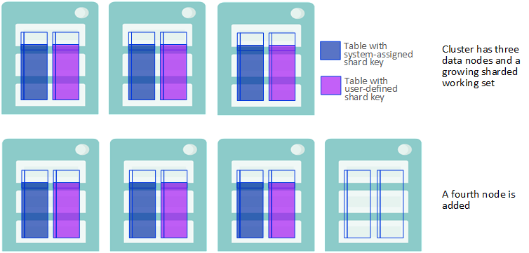
-
When sharded data is added to the scaled cluster, in the form of either rows inserted into a previously existing table or new tables created and loaded with data, their storage depends on each table’s shard key:
-
If the table has a system-assigned shard key (SASK), the new rows are stored evenly across all of the data nodes, including the new nodes.
-
If the table has a user-defined shard key (UDSK), the new rows are stored evenly across the original set of data nodes only, and not on the newly-added nodes. (If there were no existing UDSK tables before the new nodes were added, however, rows in new UDSK tables are distributed across all data nodes.)
New Data is Stored Based on the Shard Key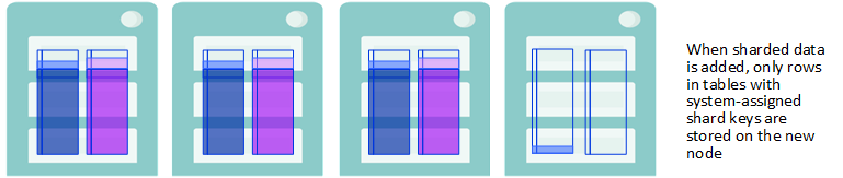
-
-
To take full advantage of parallel query processing on the cluster after adding data nodes, rebalance the sharded data stored on the cluster and enable balanced storage of data added to the cluster in the future.
Rebalancing Stores Sharded Data Evenly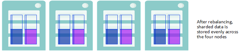
-
After rebalancing, both rows added to existing tables and the rows of newly created tables are also distributed across all data nodes, regardless of shard key. Thus, once you have rebalanced, all sharded data — in existing tables, rows added to existing tables, and new tables — is evenly distributed across all data nodes.
New Sharded Date is Stored Evenly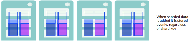
You can initiate the rebalancing operation in one of two ways:
-
Using the REBALANCE dialog, displayed by clicking Rebalance on the Management Portal’s Configure Node-Level page (System Administration > Configuration > System Configuration > Sharding > Configure Node-Level).
-
Using the $SYSTEM.Sharding.Rebalance()Opens in a new tab API call.
The Class Reference documentation for $SYSTEM.Sharding.Rebalance()Opens in a new tab explains the parameters you can specify using either interface, as well as the detailed mechanics of the rebalancing of sharded data among the data nodes.
All operations on sharded tables are permitted during a rebalancing operation with the exception of JDBC batch inserts to sharded tables (or any bulk load utility that utilizes brokered JDBC batch inserts), which return an error if attempted. An ongoing rebalancing operation may have a small negative effect on query performance and, to a lesser extent, on other operations including updates, inserts, and deletes; creating, altering and dropping tables; and assigning new shards.
If performance is of sufficient concern, you can specify a time limit on the operation, so that it can be scheduled during a low-traffic period or even a maintenance window. When the time limit is reached, the rebalancing operation (if not already complete) stops moving data (although some cleanup tasks may continue for a short time); if there remains data to be rebalanced, you can at the time of your choosing initiate another rebalancing operation, which picks up where the previous one left off. By using this approach you can fully rebalance the cluster with a series of scheduled operations of whatever length suits your needs.
When using the API call, you can also specify the minimum amount of data to be moved by the call; if it is not possible to move that much data within the specified time limit, no rebalancing occurs. Bear in mind that after you have added data nodes, you maximize performance by rebalancing the data.
Mirror Data Nodes for High Availability
An InterSystems IRIS mirror is a logical grouping of physically independent InterSystems IRIS instances simultaneously maintaining exact copies of production databases, so that if the instance providing access to the databases becomes unavailable, another can automatically and quickly take over. This automatic failover capability provides high availability for the InterSystems IRIS databases in the mirror. The High Availability Guide contains detailed information about InterSystems IRIS mirroring.
The data nodes in a sharded cluster can be mirrored to give them a failover capability, making them highly available. Each mirrored data node in a sharded cluster includes at least a failover pair of instances, one of which operates as the primary at all times, while the other operates as the backup, ready to take over as primary should its failover partner become unavailable. Data node mirrors in a sharded cluster can also include one or more DR (disaster recovery) async members, which can be promoted to failover member to replace a disabled failover partner or provide disaster recovery if both failover partners become unavailable. For typical configurations, it is strongly recommended that DR asyncs be located in separate data centers or cloud availability zones from their failover pairs to minimize the chances of all of them being affected by the same failure or outage.
A sharded cluster must be either all mirrored or all nonmirrored; that is, mirrored and nonmirrored data nodes cannot be mixed in the same cluster.
The manual procedures for configuring mirrored data nodes (using either the Management Portal or the %SYSTEM.Cluster API) recognize existing mirror configurations. This means you can configure a sharded cluster of mirrored data nodes from either nonmirrored or mirrored instances, as follows, depending on your existing circumstances and requirements::
-
When you configure nonmirrored instances as a mirrored sharded cluster, each intended primary you add is automatically configured as a mirror primary before it is attached to the cluster. You can then add another nonmirrored instance as its backup, which is automatically configured as such before it is attached to the cluster.
-
When you configure existing mirrors as a sharded cluster, each primary you add is attached to the cluster as a data node primary without any changes to its existing mirror configuration. You can then add its failover partner to the cluster by identifying it as the backup of that primary. (If the mirrored instance you added as a data node primary does not have a failover partner, you can identify a nonmirrored instance as the backup; it is automatically configured as such before it is attached to the cluster.)
-
Similarly, you can add a nonmirrored instance as a DR async member of a data node mirror to have it automatically configured as such before being attached to the cluster, or add a DR async member of an existing mirror whose failover members have already been attached to the cluster by identifying it as such.
-
In all cases, the globals databases of the cluster and master namespaces (IRISCLUSTER and IRISDM by default) are added to the mirror (the former on all data nodes and the latter on the node 1 mirror); when you configure existing mirror members, any mirrored databases remain mirrored following sharded cluster configuration.
Generally speaking, the best practice is to either begin with all unmirrored instances and configure the mirrors as part of sharded cluster deployment, or configure all of the data nodes from existing mirrors.
You can deploy a mirrored sharded cluster using any of the methods described in Deploying the Sharded Cluster. The automatic deployment methods described there all include mirroring as an option. This section provides mirrored cluster instructions to replace the final step of the manual procedures included in that section. First, execute the steps described in that section, then use one of the procedures described here to complete deployment, as follows:
-
Provision or identify the infrastructure
Note:Remember that you must provide two hosts for each mirrored data node planned in the first step. For example, if you plan calls for eight data nodes, your cluster requires 16 hosts. As is recommended for all data nodes in a sharded cluster, the two hosts comprising a mirror should have identical or at least closely comparable specifications and resources.
-
Configure the mirrored cluster nodes using either:
However you deploy the cluster, the recommended best practices are as follows:
-
Load balance application connections across all of the mirrored data nodes in the cluster.
-
Deploy and fully configure the mirrored sharded cluster, with all members of all mirrored data nodes (failover pair plus any DR asyncs) attached to the cluster, before any data is stored on the cluster. However, you can also convert an existing nonmirrored cluster to a mirrored cluster, regardless of whether there is data on it.
-
To enable transparent query execution after data node mirror failover, include compute nodes in the mirrored cluster.
The Management Portal mirroring pages and the %SYSTEM.MIRROR API allow you to specify more mirror settings than the %SYSTEM.ClusterOpens in a new tab API and Management Portal sharding pages described here; for details, see Configuring Mirroring. Even if you plan to create a cluster from nonmirrored instances and let the Management Portal or API automatically configure the mirrors, it is a good idea to review the procedures and settings in Creating a Mirror before you do so.
You cannot use the procedures in this section to deploy a mirrored namespace-level cluster. You can, however, deploy a nonmirrored namespace-level cluster as described in Deploying the Namespace-level Architecture and then convert it to a mirrored cluster as described in Convert a Nonmirrored Cluster to a Mirrored Cluster.
Mirrored Cluster Considerations
When deploying a mirrored sharded cluster, bear in mind the important points described in the following sections.
Including Compute Nodes in Mirrored Clusters for Transparent Query Execution Across Failover
Because they do not store persistent data, compute nodes are not themselves mirrored, but including them in a mirrored cluster can be advantageous even when the workload involved does not match the advanced use cases described in Deploy Compute Nodes for Workload Separation and Increased Query Throughput (which provides detailed information about compute nodes and procedures for deploying them).
If a mirrored sharded cluster is in asynchronous query mode (the default) and a data node mirror fails over while a sharded query is executing, an error is returned and the application must retry the query. There are two ways to address this problem — that is, to enable sharded queries to execute transparently across failover — as follows:
-
Set the cluster to synchronous query mode. This has drawbacks, however; in synchronous mode, sharded queries cannot be canceled, and they make greater use of the IRISTEMP database, increasing the risk that it will expand to consume all of its available storage space, interrupting the operation of the cluster.
-
Include compute nodes in the cluster. Because the compute node has a mirror connection to the mirrored data node it is assigned to, compute nodes enable transparent query execution across failover in asynchronous mode.
In view of the options, if transparent query execution across failover is important for your workload, InterSystems recommends including compute nodes in your mirrored sharded cluster (there must be at least as many as there are mirrored data nodes). If your circumstances preclude including compute nodes, you can use the RunQueriesAsync option of the $SYSTEM.Sharding.SetOption()Opens in a new tab API call (see %SYSTEM.Sharding API) to change the cluster to synchronous mode, but you should do so only if transparent query execution across failover is more important to you than the ability to cancel sharded queries and manage the size of IRISTEMP.
Creating Cluster and Master Namespaces Before Deploying
A sharded cluster is initialized when you configure the first data node, which is referred to as data node 1, or simply node 1. By default, this includes creating the cluster and master namespaces, named IRISCLUSTER and IRISDM, respectively, as well as their default globals databases and the needed mappings. However, to control the names of the cluster and master namespaces and/or the characteristics of their globals databases, you can create one or both namespaces and their default databases before configuring the cluster, then specify them during the procedure. If you plan to do this when deploying a mirrored sharded cluster, you cannot begin with unmirrored instances, but instead must take the following steps in the order shown:
-
Configure a mirror for each prospective data node, including two failover members in each.
-
Create the intended cluster namespace (using the default name IRISCLUSTER, or optionally another name) on each mirror primary, and the intended master namespace (default name IRISDM) on the primary of the mirror you will attach as data node 1. When creating each namespace, at the Select an existing database for Globals prompt select Create New Database, and at the bottom of the second page of the Database Wizard, set Mirrored database? to Yes to create the namespace’s default globals database as a mirrored database.
-
Configure the mirrors as data nodes as described in the procedures in this section, specifying the namespaces you created as the cluster and master namespaces.
Enabling IP Address Override on All Mirror Members
In some cases the hostname known to the InterSystems IRIS instance on an intended cluster node does not resolve to an appropriate address, or no hostname is available. If for this or any other reason you want other cluster nodes to communicate with a node using its IP address instead, you can enable this by providing the node’s IP address, at the Override hostname with IP address prompt in the Management Portal or as an argument to the $SYSTEM.Cluster.InitializeMirrored()Opens in a new tab and $SYSTEM.Cluster.AttachAsMirroredNode()Opens in a new tab calls. When you do this for one member of a mirror, you must do it for all mirror members, as follows:
-
When configuring unmirrored instances as mirrored data nodes, ensure that you enable IP address override for all mirror members using the prompt or calls cited above.
-
When configuring an existing mirror as a data node, however, you must enable IP address override on all members of the mirror before adding it to the cluster. Regardless of whether you are using the Management Portal or API procedure, do this on each node by opening an InterSystems Terminal window and (in any namespace) calling $SYSTEM.Sharding.SetNodeIPAddress()Opens in a new tab (see %SYSTEM.Sharding API), for example:
set status = $SYSTEM.Sharding.SetNodeIPAddress("00.53.183.209")Once you have used this call on a node, you must use the IP address you specified, rather than the hostname, to refer to the node in other API calls, for example, when attaching a mirror backup to the cluster using the $SYSTEM.Cluster.AttachAsMirroredNode()Opens in a new tab call, in which you must identify the attached primary.
Updating a Mirrored Cluster’s Metadata
If you make mirroring changes to the mirrored data nodes of a cluster outside of the %SYSTEM.ClusterOpens in a new tab API and Management Portal sharding pages, for example using the Management Portal mirroring pages or the SYS.MirrorOpens in a new tab API, you must update the mirrored cluster’s metadata after doing so; for more information, see Updating the Cluster Metadata for Mirroring Changes.
Configure the Mirrored Cluster Using the Management Portal
For information about opening the Management Portal in your browser, see the instructions for an instance deployed in a container or one installed from a kit.
To configure the mirrored cluster using the Management Portal, follow these steps:
-
On both the intended node 1 primary and the intended node 1 backup, open the Management Portal for the instance, select System Administration > Configuration > System Configuration > Sharding > Enable Sharding, and on the dialog that displays, click OK (here is no need to change the Maximum Number of ECP Connections setting). Then restart the instance as indicated (there is no need to close the browser window or tab containing the Management Portal; you can simply reload it after the instance has fully restarted).
-
On the intended primary, navigate to the Configure Node-Level page (System Administration > Configuration > System Configuration > Sharding > Configure Node-Level) and click the Configure button.
-
On the CONFIGURE NODE-LEVEL CLUSTER dialog, select Initialize a new sharded cluster on this instance and respond to the prompts that display as follows:
-
Select a Cluster namespace and Master namespace from the respective drop-downs, which both include
-
The default names (IRISCLUSTER and IRISDM) of new namespaces to be created, along with their default globals databases.
-
All eligible existing namespaces.
Initializing a sharded cluster creates by default cluster and master namespaces named IRISCLUSTER and IRISDM, respectively, as well as their default globals databases and the needed mappings. However, to control the names of the cluster and master namespaces and the characteristics of their globals databases, you can create one or both namespaces and their default databases before configuring the cluster, then specify them during the procedure. For example, given the considerations discussed in Globals Database Sizes, you may want to do this to control the characteristics of the default globals database of the cluster namespace, or shard database, which is replicated on all data nodes in the cluster.
Note:If you want to use existing namespaces when configuring existing mirrors as a sharded cluster, follow the procedure in Creating Cluster and Master Namespaces Before Deploying.
If the default globals database of an existing namespace you specify as the cluster namespace contains any globals or routines, initialization will fail with an error.
-
-
In some cases, the hostname known to InterSystems IRIS does not resolve to an appropriate address, or no hostname is available. If for this or any other reason, you want other cluster nodes to communicate with this node using its IP address instead, enter the IP address at the Override hostname prompt.
-
Select Enable Mirroring, and add the arbiter’s location and port if you intend to configure one (which is a highly recommended best practice).
-
-
Click OK to return to the Configure Node-Level page, which now includes two tabs, Shards and Sharded Tables. Node 1 is listed under Shards, including its cluster address (which you will need in the next procedure), so you may want to leave the Management Portal for node 1 open on the Configure Node-Level page, for reference. The mirror name is not yet displayed because the backup has not yet been added.
-
On the intended node 1 backup, navigate to the Configure Node-Level page as for the primary, and click the Configure button.
-
On the CONFIGURE NODE-LEVEL CLUSTER dialog, select Add this instance to an existing sharded cluster and respond to the prompts that display as follows:
-
Enter the address displayed for the node 1 primary on the Shards tab of the Configure Node-Level page (as described in an earlier step) as the Cluster URL.
-
Select data at the Role prompt to configure the instance as a data node.
-
In some cases, the hostname known to InterSystems IRIS does not resolve to an appropriate address, or no hostname is available. If for this or any other reason, you want other cluster nodes to communicate with this node using its IP address instead, enter the IP address at the Override hostname prompt.
-
Select Mirrored cluster and do the following:
-
Select backup failover from the Mirror role drop-down.
-
If you configured an arbiter when initializing node 1 in a previous step, add the same arbiter location and port as you did there.
-
-
-
Click OK to return to the Configure Node-Level page, which now includes two tabs, Shards and Sharded Tables. The node 1 primary and backup you have configured so far are listed under Shards in the node 1 position, with the assigned mirror name included.
-
For each remaining mirrored data node, repeat the previous steps, beginning with the Enable Sharding option and a restart for both instances. When you add the primary to the cluster, enter the node 1 primary’s address as the Cluster URL, as described in the preceding, but when you add the backup, enter the address of the primary you just added as the Cluster URL (not the address of the node 1 primary).
-
When each mirrored data node has been added, on one of the primaries in the cluster, navigate to the Configure Node-Level page and click Verify Shards to verify that the new mirrored node is correctly configured and can communicate with the others. You can also wait until you have added all the mirrored data nodes to do this, or you can make the verification operation automatic by clicking the Advanced Settings button and selecting Automatically verify shards on assignment on the ADVANCED SETTINGS dialog. (Other settings in this dialog should be left at the defaults when you deploy a sharded cluster.)
Configure the Mirrored Cluster Nodes Using the %SYSTEM.Cluster API
To configure the mirrored cluster using the API, do the following:
-
On the intended node 1 primary, open the InterSystems Terminal for the instance and call the $SYSTEM.Cluster.InitializeMirrored()Opens in a new tab method, for example:
set status = $SYSTEM.Cluster.InitializeMirrored()Note:To see the return value (for example, 1 for success) for the each API call detailed in these instructions, enter:
zw statusIf a call does not succeed, display the user-friendly error message by entering:
do $SYSTEM.Status.DisplayError(status)This call initializes the cluster on the node in the same way as $SYSTEM.Cluster.Initialize()Opens in a new tab, described in Configure Node 1; review that section for explanations of the first four arguments (none required) to InitializeMirrored(), which are the same as for Initialize(). If the instance is not already a mirror primary, you can use the next five arguments to configure it as one; if it is already a primary, these are ignored. The mirror arguments are as follows:
-
Arbiter host
-
Arbiter port
-
Directory containing the Certificate Authority certificate, local certificate, and private key file required to secure the mirror with TLS, if desired. The call expects the files to be named CAFile.pem, CertificateFile.pem, and PrivateKeyFile.pem, respectively.
-
Name of the mirror.
-
Name of this mirror member.
Note:The InitializeMirrored() call returns an error if
-
The current InterSystems IRIS instance is already a node of a sharded cluster.
-
The current instance is already a mirror member, but not the primary.
-
You specify (in the first two arguments) a cluster namespace or master namespace that already exists, and its globals database is not mirrored.
-
-
On the intended node 1 backup, open the Terminal for the InterSystems IRIS instance and call $SYSTEM.Cluster.AttachAsMirroredNode()Opens in a new tab, specifying the host and superserver port of the node 1 primary as the cluster URL in the first argument, and the mirror role backup in the second, for example:
set status = $SYSTEM.Cluster.AttachAsMirroredNode("IRIS://node1prim:1972","backup")If you supplied an IP address as the fourth argument to InitializeMirrored() when initializing the node 1 primary, use the IP address instead of the hostname to identify node 1 in the first argument, for example:
set status = $SYSTEM.Cluster.AttachAsMirroredNode("IRIS://100.00.0.01:1972","backup")Note:The default superserver port number of a noncontainerized InterSystems IRIS instance that is the only such on its host is 1972. To see or set the instance’s superserver port number, select System Administration > Configuration > System Configuration > Memory and Startup in the instance’s Management Portal. (For information about opening the Management Portal for the instance and determining the superserver port, see the instructions for an instance deployed in a container or one installed from a kit.)
This call attaches the node as a data node in the same way as $SYSTEM.Cluster.AttachAsDataNode()Opens in a new tab, as described in Configure the Remaining Data Nodes, and ensures that it is the backup member of the node 1 mirror. If the node is backup to the node 1 primary before you issue the call — that is, you are initializing an existing mirror as node 1 — the mirror configuration is unchanged; if it is not a mirror member, it is added to the node 1 primary’s mirror as backup. Either way, the namespace, database, and mappings configuration of the node 1 primary are replicated on this node. (The third argument to AttachAsMirroredNode is the same as the second for AttachAsDataNode, that is, the IP address of the host, included if you want the other cluster members to use it in communicating with this node.)
If there are any intended DR async members of the node 1 mirror, use AttachAsMirroredNode() to attach them, with the substitution of drasync for backup as the second argument, for example:
set status = $SYSTEM.Cluster.AttachAsMirroredNode("IRIS://node1prim:1972","drasync")As with attaching a backup, if you are attaching an existing member of the mirror, its mirror configuration is unchanged; otherwise, the needed mirror configuration is added. Either way, the namespace, database, and mappings configuration of the node 1 primary are replicated on the new node.
Note:Attempting to attach an instance that is a member of a different mirror from that of the node 1 primary causes an error.
-
To configure mirrored data nodes other than node 1, use $SYSTEM.Cluster.AttachAsMirroredNode()Opens in a new tab to attach both the failover pair and any DR asyncs to the cluster, as follows:
-
When adding a primary, specify any existing primary in the cluster URL and primary as the second argument. If the instance is not already the primary in a mirror, use the fourth argument and the four that follow to configure it as the first member of a new mirror; the arguments are as listed for the InitializeMirrored() call in the preceding. If the instance is already a mirror primary, the mirror arguments are ignored if provided.
-
When adding a backup, specify its intended primary in the cluster URL and backup as the second argument. If the instance is already configured as backup in the mirror in which the node you specify is primary, its mirror configuration is unchanged; if it is not yet a mirror member, it is configured as the second failover member.
-
When adding a DR async, specify its intended primary in the cluster URL and drasync as the second argument. If the instance is already configured as a DR async in the mirror in which the node you specify is primary, its mirror configuration is unchanged; if it is not yet a mirror member, it is configured as a DR async.
Note:The AttachAsMirroredNode() call returns an error if
-
The current InterSystems IRIS instance is already a node in a sharded cluster.
-
The role primary is specified and the cluster node specified in the cluster URL (first argument) is not a mirror primary, or the current instance belongs to a mirror in a role other than primary.
-
The role backup is specified and the cluster node specified in the first argument is not a mirror primary, or is primary in a mirror that already has a backup failover member.
-
The role drasync is specified and the cluster node specified in the first argument is not a mirror primary.
-
The role backup or drasync is specified and the instance being added already belongs to a mirror other than the one whose primary you specified.
-
The cluster namespace (or master namespace, when adding the node 1 backup) already exists on the current instance and its globals database is not mirrored.
-
-
When you have configured all of the data nodes, you can call the $SYSTEM.Cluster.ListNodes()Opens in a new tab method to list them. When a cluster is mirrored, the list indicates the mirror name and role for each member of a mirrored data node, for example:
set status = $system.Cluster.ListNodes()
NodeId  NodeType    Host          Port   Mirror  Role
1       Data        node1prim     1972   MIRROR1 Primary
1       Data        node1back     1972   MIRROR1 Backup
1       Data        node1dr       1972   MIRROR2 DRasync
2       Data        node2prim     1972   MIRROR2 Primary
2       Data        node2back     1972   MIRROR2 Backup
2       Data        node2dr       1972   MIRROR2 DRasync
Convert a Nonmirrored Cluster to a Mirrored Cluster
This section provides a procedure for converting an existing nonmirrored sharded cluster to a mirrored cluster. The following is an overview of the tasks involved:
-
Provision and prepare at least enough new nodes to provide a backup for each existing data node in the cluster.
-
Create a mirror on each existing data node and then call $SYSTEM.Sharding.AddDatabasesToMirrors()Opens in a new tab on node 1 to automatically convert the cluster to a mirrored configuration.
-
Create a coordinated backup of the now-mirrored master and shard databases on the existing data nodes (the first failover member in each mirror) as described in Coordinated Backup and Restore of Sharded Clusters.
-
For each intended second failover member (new node), select the first failover member (existing data node) to be joined, then create databases on the new node corresponding to the mirrored databases on the first failover member, add the new node to the mirror as second failover member, and restore the databases from the backup made on the first failover member to automatically add them to the mirror.
-
To add a DR async to the failover pair you have created in a data node mirror, create databases on the new node corresponding to the mirrored databases on the first failover member, add the new node to the mirror as a DR async, and restore the databases from the backup made on the first failover member to automatically add them to the mirror.
-
Call $SYSTEM.Sharding.VerifyShards()Opens in a new tab on any of the mirror primaries (original data nodes) to validate information about the backups and add it to the sharding metadata.
You can perform the entire procedure within a single maintenance window (that is, a scheduled period of time during which the application is offline and there is no user activity on the cluster), or you can split it between two maintenance windows, as noted in the instructions.
The detailed steps are provided in the following. If you are not already familiar with it, review Deploy the Cluster Using the %SYSTEM.Cluster API before continuing. Familiarity with mirror configuration procedures, as described in Configuring Mirroring, is also helpful but not required; the steps in this procedure provide links where appropriate.
When a node-level nonmirrored cluster is converted to mirrored using this procedure, it becomes a namespace-level cluster, and can be managed and modified using only the %SYSTEM.Sharding API and the namespace-level pages in the Management Portal.
-
To use this procedure, you must know the names of the cluster’s cluster namespace and master namespace, which were determined when you deployed the cluster. For example, step 4 in Configure Data Node 1 discusses selecting the cluster and master namespaces; similarly, the discussion of the initial API call in Configure Node 1 includes determining the cluster and master namespaces.
-
Prepare the nodes that are to be added to the cluster as backup failover members according to the instructions in Provision or identify the infrastructure and Deploy InterSystems IRIS on the Data Nodes. The host characteristics and InterSystems IRIS configuration of the prospective backups should be the same as the existing data nodes in all respects (see Mirror Configuration Guidelines).
Note:It may be helpful to make a record, by hostnames or IP addresses, of the intended first failover member (existing data node) and second failover member (newly added node) of each failover pair.
-
Begin a maintenance window for the sharded cluster.
-
On each current data node, start the ISCAgent, then create a mirror and configure the first failover member.
-
To convert the cluster to a mirrored configuration — that is, to incorporate the mirrors you created in the previous step into the cluster’s configuration and metadata — open the InterSystems Terminal for the instance on node 1 and in the master namespace call the $SYSTEM.Sharding.AddDatabasesToMirrors()Opens in a new tab method (see %SYSTEM.Sharding API) as follows:
set status = $SYSTEM.Sharding.AddDatabasesToMirrors()Note:To see the return value (for example, 1 for success) for the each API call detailed in these instructions, enter:
zw statusReviewing status after each call is a good general practice, as a call might fail silently under some circumstances. If a call does not succeed (status is not 1), display the user-friendly error message by entering:
do $SYSTEM.Status.DisplayError(status)The AddDatabasesToMirrors() call does the following:
-
Adds the master and shard databases on node 1 (see Initialize node 1) and the shard databases on the other data nodes to their respective mirrors.
-
Reconfigures all ECP connections between nodes as mirror connections, including those between compute nodes (if any) and their associated data nodes.
-
Reconfigures remote databases on all data nodes and adjusts all related mappings accordingly.
-
Updates the sharding metadata to reflect the reconfigured connections, databases, and mappings.
When the call has successfully completed, the sharded cluster is in a fully usable state (although failover is not yet possible because the backup failover members have not yet been added).
-
-
Perform a coordinated backup of the data nodes (that is, one in which all nodes are backed up at the same logical point in time). Specifically, on each of the first failover members (the existing data nodes), back up the shard database, and on node 1, also back up the master database. Before the backup, confirm that you have identified the right databases by examining the instance’s configuration parameter file (CPF), as follows:
-
Identify the shard database by finding the [Map.clusternamespace] section of the CPF — for example, if the cluster namespace is CLUSTERNAMESPACE, the section would be [Map.CLUSTERNAMESPACE] — and locating the IRIS.SM.Shard and IS.* global prefix mappings, the target of which is the shard database. Additional global prefixes may be mapped to the shard database, as shown in the following, which identifies the shard database as SHARDDB.
[Map.CLUSTERNAMESPACE] Global_IRIS.SM.Shard=SHARDB Global_IRIS.Shard.*=SHARDDB Global_IS.*=SHARDDB Package_IRIS.Federated=SHARDDB -
On node 1, also locate the [Namespaces] section, where the master database is shown after the master namespace as its default globals database. For example, the following shows MASTERDB, the master database, as the default globals databases of MASTERNAMESPACE.
[Namespaces]
%SYS=IRISSYS
CLUSTERNAMESPACE=SHARDDB
MASTERNAMESPACE=MASTERDB
USER=USER
-
-
Optionally, end the current maintenance window and allow application activity while you prepare the prospective second failover members and DR async mirror members (if any) in the following steps.
-
On each node to be added to the cluster as a second failover member or DR async:
-
Create a namespace with the same name as the cluster namespace on the intended first failover member (CLUSTERNAMESPACE in the examples above), configuring as its default globals database a local database with the same name as the shard database on the first failover member (SHARDDB in the examples).
-
On the intended second failover member or DR async to be added to the node 1, also create a namespace with the same name as the master namespace on the intended first failover member, configuring as its default globals database a local database with the same name as the master database. Using the examples above, you would create a MASTERNAMESPACE namespace with a database called MASTERDB as its default globals database.
-
If not in a maintenance window, start a new one.
-
On each new node, perform the tasks required to add any nonmirrored instance as the second failover member or a DR async member of an existing mirror that includes mirrored databases containing data, as follows:
-
Configure the node as the second failover member of the intended mirror or (after the second failover member has been configured) configure it as a DR async member.
-
On the newly configured member, restore the shard database from the backup made on the first failover member; on a newly configured member of the node 1 mirror (second failover or DR async), also restore the master database from the backup made on the node 1 first failover member.
-
Activate and catch up the master database and the cluster databases (not necessary if you created the backups using online backup).
Note:Sharding automatically updates the cluster namespace definition, creates all the needed mappings, ECP server definitions, and remote database definitions, and propagates to the shards any user-defined mappings in the master namespace. Therefore, the only mappings that must be manually created during this process are any user-defined mappings in the master namespace, which must be created only in the master namespace on the node 1 second failover member. ECP server definitions and remote database definitions need not be manually copied.
-
-
Open the InterSystems Terminal for the instance on any of the primaries (original data nodes) and in the cluster namespace (or the master namespace on node 1) call the $SYSTEM.Sharding.VerifyShards()Opens in a new tab method (see %SYSTEM.Sharding API) as follows:
set status = $SYSTEM.Sharding.VerifyShards()This call automatically adds the necessary information about the second failover members of the mirrors to the sharding metadata.
Note:All of the original cluster nodes must be the current primary of their mirrors when this call is made. Therefore, if any mirror has failed over since the second failover member was added, arrange a planned failover back to the original failover member before performing this step. (For one procedure for planned failover, see Maintenance of Primary Failover Member; for information about using the iris stop command for the graceful shutdown referred to in that procedure, see Controlling InterSystems IRIS Instances.)
With the completion of the last step above, the maintenance window can be terminated. However, InterSystems strongly recommends testing each mirror by executing a planned failover (see above) before the cluster goes into production.
Updating the Cluster Metadata for Mirroring Changes
When you make changes to the mirror configuration of one or more data nodes in a mirrored cluster using any means other than the API or Management Portal procedures described here — that is, using the Mirroring pages of the Management Portal, the ^MIRROR routine, or the SYS.MIRROR API) — you must update the cluster’s metadata by either calling $SYSTEM.Sharding.VerifyShards()Opens in a new tab (see %SYSTEM.Sharding API) in the cluster namespace or using the Verify Shards button on the Configure Node-Level page of the Management Portal (see Configure the Mirrored Cluster Using the Management Portal) on any current primary failover member in the cluster. For example, if you perform a planned failover, add a DR async, demote a backup member to DR async, or promote a DR async to failover member, verifying the shards updates the metadata to reflect the change. Updating the cluster metadata is an important element in maintaining and utilizing a disaster recovery capability you have established by including DR asyncs in your data node mirrors; for more information, see Disaster Recovery of Mirrored Sharded Clusters.
A cluster’s shards can be verified after every mirroring configuration operation, or just once after a sequence of operations, but if operations are performed while the cluster is online, it is advisable to verify the shards immediately after any operation which adds or removes a failover member.
Deploy Compute Nodes for Workload Separation and Increased Query Throughput
For advanced use cases in which extremely low query latencies are required, potentially at odds with a constant influx of data, compute nodes can be added to provide a transparent caching layer for servicing queries. Each compute node caches the sharded data on the data node it is associated with, as well as nonsharded data when necessary. When a cluster includes compute nodes, read-only queries are automatically executed in parallel on the compute nodes, rather than on the data nodes; all write operations (insert, update, delete, and DDL operations) continue to be executed on the data nodes. This division of labor separates the query and data ingestion workloads while maintaining the advantages of parallel processing and distributed caching, improving the performance of both. Assigning multiple compute nodes per data node can further improve the query throughput and performance of the cluster.
When compute nodes are added to a cluster, they are automatically distributed as evenly as possible across the data nodes. Adding compute nodes yields significant performance improvement only when there is at least one compute node per data node; since a cluster is only as fast as its slowest data node, the most efficient use of resources, in general, is to assign the same number of compute nodes to each data node. Because compute nodes support query execution only and do not store any data, their hardware profile can be tailored to suit those needs, for example by emphasizing memory and CPU and keeping storage to the bare minimum.

For information about planning compute nodes and load balancing application connections to clusters with compute nodes, see Plan Compute Nodes.
You can add compute nodes to a sharded cluster using any of the deployment methods described in Deploying the Sharded Cluster. The automatic deployment methods described there all include compute nodes as an option. This section provides additional manual instructions for deploying compute nodes. First, manually deploy and configure the sharded cluster using the steps described in that section, then complete deployment with the steps described here, as follows:
-
Provision or identify the infrastructure
Note:Include hosts for your planned compute nodes along with those for the planned data nodes. For example, if you plan calls for eight data nodes and eight compute nodes, your cluster requires 16 hosts. All nodes in a sharded cluster should have identical or at least closely comparable specifications and resources, with the exception of storage for compute nodes, which do not use any in their sharded cluster role.
-
Configure the data nodes using either the Management Portal or the %SYSTEM.Cluster API.
-
Add compute nodes using either the Management Portal or the %SYSTEM.Cluster API, as described in the following sections.
Configure or Deploy Compute Nodes Using the Management Portal
When you add a compute node to a cluster, it is assigned to a data node that previously had the minimum number of associated compute nodes, so as to automatically balance compute nodes across the data nodes. The procedure is the same regardless of whether the cluster is mirrored.
For information about opening the Management Portal in your browser, see the instructions for an instance deployed in a container or one installed from a kit.
To add an instance on a networked system to your cluster as a compute node, use the following steps.
-
Open the Management Portal for the instance, select System Administration > Configuration > System Configuration > Sharding > Enable Sharding, and on the dialog that displays, click OK. (The value of the Maximum Number of ECP Connections setting need not be changed as the default is appropriate for virtually all clusters.)
-
Restart the instance. (There is no need to close the browser window or tab containing the Management Portal; you can simply reload it after the instance has fully restarted.)
-
Navigate to the Configure Node-Level page (System Administration > Configuration > System Configuration > Sharding > Configure Node-Level) and click the Configure button.
-
On the CONFIGURE NODE-LEVEL CLUSTER dialog, select Add this instance to an existing sharded cluster and respond to the prompts that display as follows:
-
Enter the cluster URL, which is the address displayed for any node on the Shards tab of the Configure Node-Level page on an instance that already belongs to the cluster, as described in Configure the remaining data nodes.
Note:If the cluster is mirrored, enter the address of a primary data node or a compute node, but not a backup data node.
-
Select compute at the Role prompt to configure the instance as a data node.
-
In some cases, the hostname known to InterSystems IRIS does not resolve to an appropriate address, or no hostname is available. If for this or any other reason, you want other cluster nodes to communicate with this node using its IP address instead, enter the IP address at the Override hostname prompt.
-
The Mirrored cluster check box is not available, because configuration of compute nodes is the same regardless of mirroring (except for the cluster URL provided, as above.)
-
-
Click OK to return to the Configure Node-Level page, which now includes two tabs, Shards and Sharded Tables. The data and compute nodes you have configured so far are listed under Shards, starting with node 1, and showing which data node each compute node is assigned to.
Click Verify Shards to verify that the compute node is correctly configured and can communicate with the others.
Note:If you have many compute nodes to configure, you can make the verification operation automatic by clicking the Advanced Settings button and selecting Automatically verify shards on assignment on the ADVANCED SETTINGS dialog. (Other settings in this dialog should be left at the defaults when you deploy a sharded cluster.)
Deploy Compute Nodes Using the %SYSTEM.Cluster API
To add an instance on a networked system to your cluster as a compute node, open the InterSystems Terminal for the instance and call the $SYSTEM.Cluster.AttachAsComputeNode()Opens in a new tab method specifying the hostname of an existing cluster node and the superserver port of its InterSystems IRIS instance, for example:
set status = $SYSTEM.Cluster.AttachAsComputeNode("IRIS://datanode2:1972")
To see the return value (for example, 1 for success) for the each API call detailed in these instructions, enter:
zw status
If a call does not succeed, display the user-friendly error message by entering:
do $SYSTEM.Status.DisplayError(status)
If you provided the IP address of the template node when configuring it (see Configure node 1), use the IP address instead of the hostname.
set status = $SYSTEM.Cluster.AttachAsComputeNode("IRIS://100.00.0.01:1972")
If you want other nodes to communicate with this one using its IP address, specify the IP address as the second argument.
From the perspective of another node (which is what you need in this procedure), the superserver port of a containerized InterSystems IRIS instance depends on which host port the superserver port was published or exposed as when the container was created. For details on and examples of this, see Running an InterSystems IRIS Container with Durable %SYS and Running an InterSystems IRIS Container: Docker Compose Example and see Container networkingOpens in a new tab in the Docker documentation.
The default superserver port number of a noncontainerized InterSystems IRIS instance that is the only such on its host is 1972. To see or set the instance’s superserver port number, select System Administration > Configuration > System Configuration > Memory and Startup in the instance’s Management Portal. (For information about opening the Management Portal for the instance and determining the superserver port, see the instructions for an instance deployed in a container or one installed from a kit.)
If the cluster node you identify in the first argument is a data node, it is used as the template; if it is a compute node, the data node to which it is assigned is used as the template. The AttachAsComputeNode() call does the following:
-
Enables the ECP and sharding services
-
Associates the new compute node with a data node that previously had the minimum number of associated compute nodes, so as to automatically balance compute nodes across the data nodes.
-
Creates the cluster namespace, configuring it to match the settings on the template node (specified in the first argument), as described in Configure Node 1, and creating all needed mappings.
-
Sets all SQL configuration options to match the template node.
If a namespace of the same name as the cluster namespace already exists on the new compute node, it is used as the cluster namespace, and only the mappings are replicated.
If you want other cluster nodes to communicate with this node using its IP address instead of its hostname, supply the IP address as the second argument.
The AttachAsComputeNode() call returns an error if the InterSystems IRIS instance is already a node in a sharded cluster.
When you have configured all of the compute nodes, you can call the $SYSTEM.Cluster.ListNodes()Opens in a new tab method to list them, for example:
set status = $system.Cluster.ListNodes()
NodeId  NodeType    DataNodeId    Host          Port
1       Data                      datanode1     1972
2       Data                      datanode2     1972
3       Data                      datanode3     1972
1001    Compute     1             computenode1  1972
1002    Compute     2             computenode2  1972
1003    Compute     3             computenode3  1972
When compute nodes are deployed, the list indicates the node ID of the data node that each compute node is assigned to. You can also use the $SYSTEM.Cluster.GetMetadata()Opens in a new tab retrieve metadata for the cluster, including the names of the cluster and master namespaces and their default globals databases and settings for the node on which you issue the call.
Install Multiple Data Nodes per Host
With a given number of systems hosting data nodes, configuring multiple data node instances per host using the %SYSTEM.Sharding API (you cannot do so with the %SYSTEM.Cluster API or the Management Portal) can significantly increase data ingestion throughput. Therefore, when achieving the highest data ingestion throughput at the lowest cost is a concern, this may be achieved by configuring two or three data node instances per host. The gain achieved will depend on server type, server resources, and overall workload. While adding to the total number of systems might achieve the same throughput gain, or more (without dividing a host system’s memory among multiple database caches), adding instances is less expensive than adding systems.